- SOLIDWORKS FLOW SIMULATION PROPELLER HOW TO
- SOLIDWORKS FLOW SIMULATION PROPELLER SOFTWARE
- SOLIDWORKS FLOW SIMULATION PROPELLER PROFESSIONAL
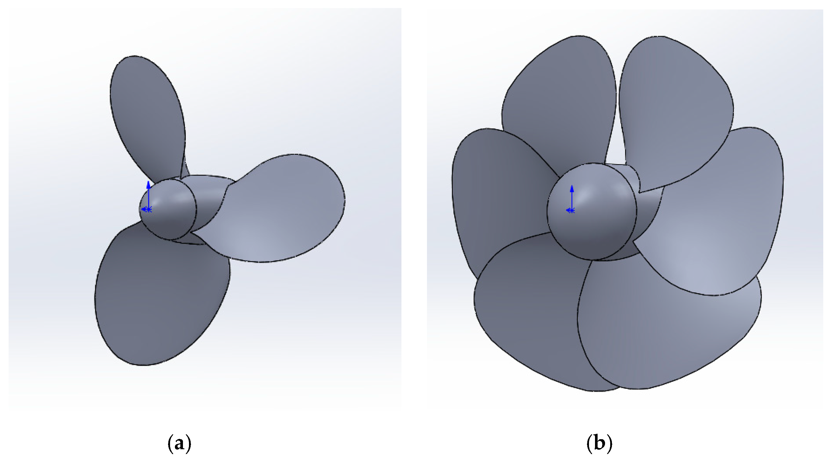
Therefore, the local rotating region (sliding mesh) technique will be used. Theoretically, the rotor blades should produce flow fields that may not axially symmetric. Before jumping into Flow Simulation tool, we first need to create a couple of parts that represent the rotating region of our study. Here come the suggested set up to perform the helicopter rotor simulation.

Hence, flow simulation is to be done to test the maximum lift the configuration can produce as well as the maximum torque the rotor need to withstand during the spinning. Different pitch angle will produce different lift due to the aerodynamic lift contribution. The diagram below shows the pitch angle at +10 degrees. Let the pitch angle range from -10 degrees to +10 degrees where zero being neutral or no lift produced. The amount of that the rotor able to produce is dependent to the pitch angle of the rotor. Helicopter blades are designed to operate at a constant RPM. To allow the helicopter to lift, the spinning rotor needs to generate the lift more than 20N (4.5 Ib) to make the lifting possible. The pressure difference between upper and lower aerofoil surface produces a perpendicular force which is known as lift.įrom Hawk Ridge Systems, the RC helicopter is designed to have a mass of 2kg. Whereas, for lower surface of the aerofoil, the air velocity is lower than the upper surface and producing higher pressure. As the aerofoil is moving toward the airflow, the air at the upper surface of the wing experience higher velocity and reduced pressure. To better understand the lift, a pressure difference around the aerofoil is used. Lift is defined by the component of force generated by solid body that is perpendicular to the flow direction. As mentioned, RC helicopter flies when the lift is sufficiently high to rise the RC helicopter. Īssume that now you have a RC helicopter model and you would like to know the performance of the helicopter by varying the rotor spinning rate. The reference for this case study is from Hawk Ridge Systems.

SOLIDWORKS FLOW SIMULATION PROPELLER HOW TO
Hence, in this case study, we shall focus on how to simulate the helicopter rotor as well as the flow around the it. As it rotates, it creates a force called lift that allows the UAV to rise into the air as well as giving high manoeuvrability to the aircraft itself. The propeller of UAVs is also called as spinning wing. Since UAV is an aircraft that travels with lower speed, hence most of the UAVs are installed with propeller. The flights of UAVs may operate with various degrees of autonomy: either under remote control by human operator or autonomously by onboard computers. The introduction of unmanned aerial vehicle (UAV), commonly known as drone has made a big leapt towards a smaller aircraft with greater mobility.
SOLIDWORKS FLOW SIMULATION PROPELLER PROFESSIONAL

SOLIDWORKS Product Data Management (PDM).
SOLIDWORKS FLOW SIMULATION PROPELLER SOFTWARE
Solidworks Tutorial: Beginner Flow Simulation Tutorial Introduction Solidworks has built in computational flow dynamics capabilities that are very useful for determining the effect of fluid flow on a solid model.įlow Design software offers flow simulation and wind tunnel simulator tools that enable flow analysis. Whether you are developing an automobile, the wing of an airplane, or an exhaust valve, using SolidWorks.

SolidWorks Flow Simulation can be used in a diverse array of applications and has been designed to be extremely flexible. I try to do it with a turning gear and I'm getting a velocity discontinuity between my rotating region boundary and the free. Tutorial how to do a flow simulation to a rotating propeller. SOLIDWORKS Flow Simulation gives product engineers access to powerful CFD (computational fluid dynamics) analysis capabilities that help enable them to speed up product. SOLIDWORKS Flow Simulation 2016 Datasheet. SOLIDWORKS Flow Simulation - takes the complexity out of Computational Fluid Dynamics (CFD). It models airflow around design concepts to help test ideas early in the development cycle. Flow Design is virtual wind tunnel software for product designers, engineers, and architects. Efficient fluid flow simulation, heat transfer, and fluid forces critical to your design's success with SolidWorks Flow Simulation Software.


 0 kommentar(er)
